Catenary Curve in Modo Schematic
2023-04-20
I wanted to learn more about Modo's Procedural tools. And had just recently seen great video about making a procedural rope bridge in Blender using Geometry Nodes by Erindale. So as a more simple exercise I figured I would create the curve for the ropes in a potentially future rope bridge.
Making a line between points
Create two locator items, and one mesh item (or using the empty mesh item already in a new scene). The mesh item will be our final geometry and have all user channels we want to use for controlling number of segments, and later on the slack of the line. The locators will be start and end points for the line.
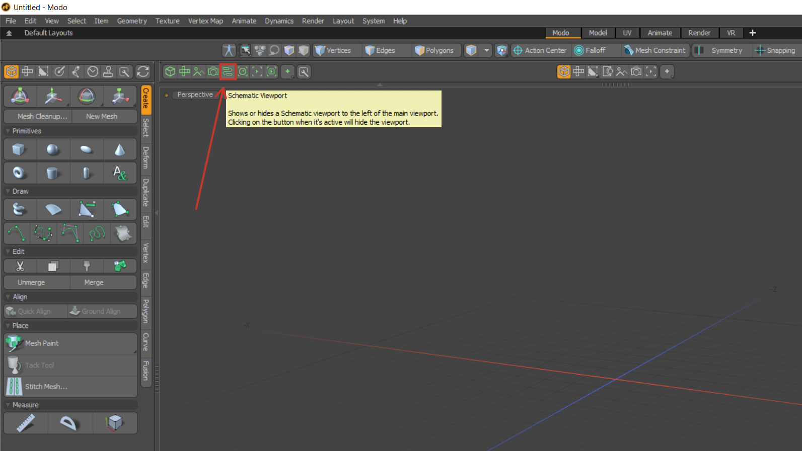
Open a Schematic View. Since version 15 of Modo this should be available in the default layout, among the icons on the left above the 3D Viewport. Drag all the items into the Schematic View then "Add..." an Array Blend node. Right click the locators to Add Channel and find the World Position. Connect the World Position of the locators to Input A and Input B of the Array Blend.
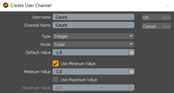
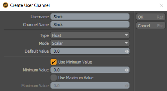
Add a user channel for controlling the number of segments in the line. So in Schematic view, right click the mesh item and find "Add User Channel...". In the prompt I set the name to "Count" for the number of segments I want it to have, made it an integer and set it to a default and minimum value of 1.
Array Blend node also has a channel called Count but this is not in the Schematic View by default. We can add this by finding the channel in the channel list. Drag and drop it into the Schematic View. Or on the node's right-click menu like we did before with "Add Channel" and find Count there.
To make our user channel Count become the number of segments in the line, add a Basic Math:Add node. Connect the user channel Count to the first input of the add, and in the properties set the second input value to 1. Connect the output of the add node to the Count channel of the Array Blend.
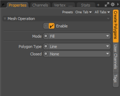
Add a Create Polygons Mesh Operation to our mesh item. Connect the output Array of our Array Blend to the Positions channel of Create Polygons. Change the Mode to Fill and the Polygon Type to Line.
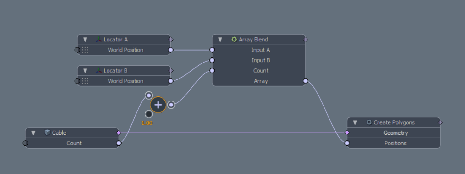
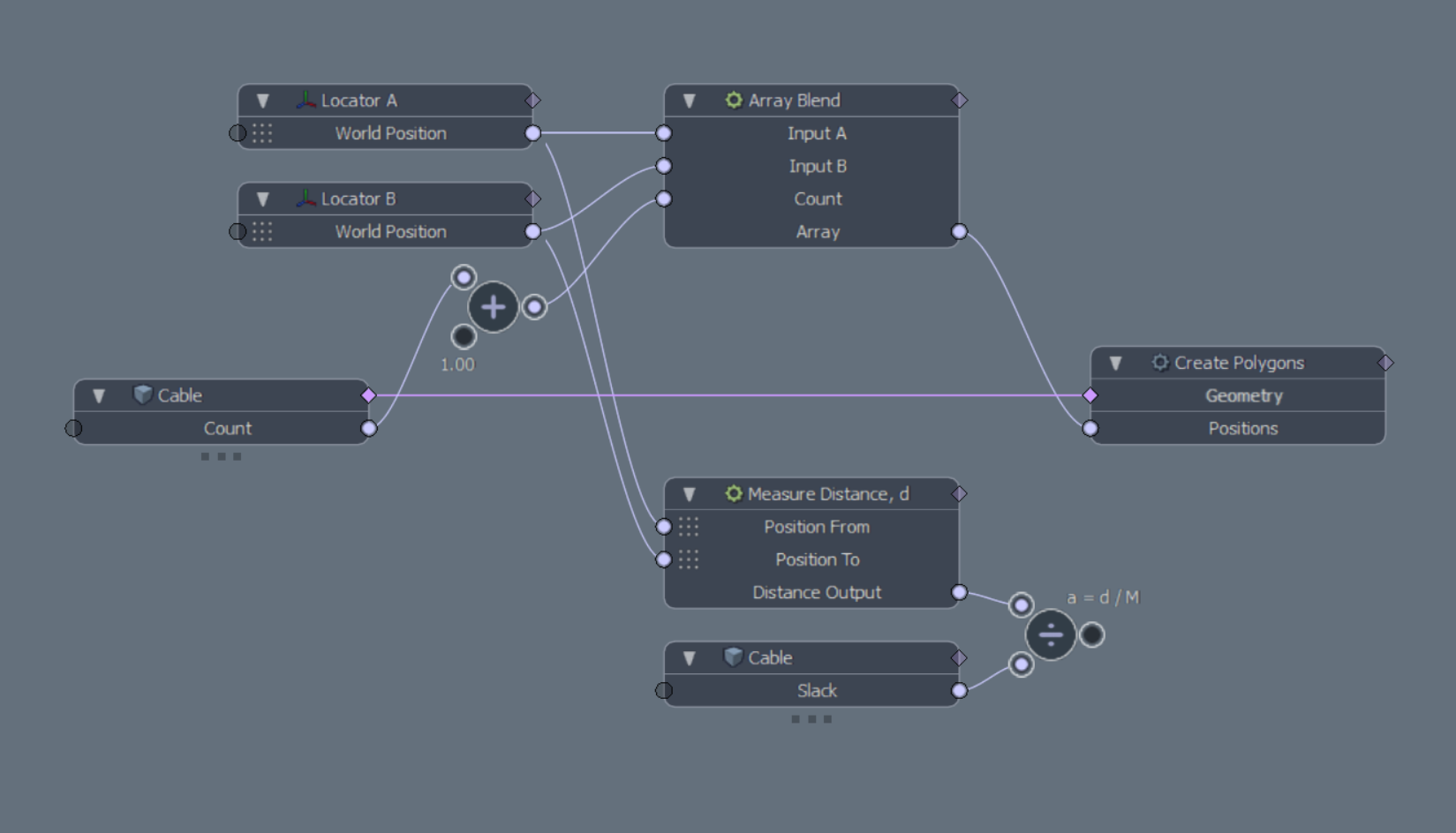
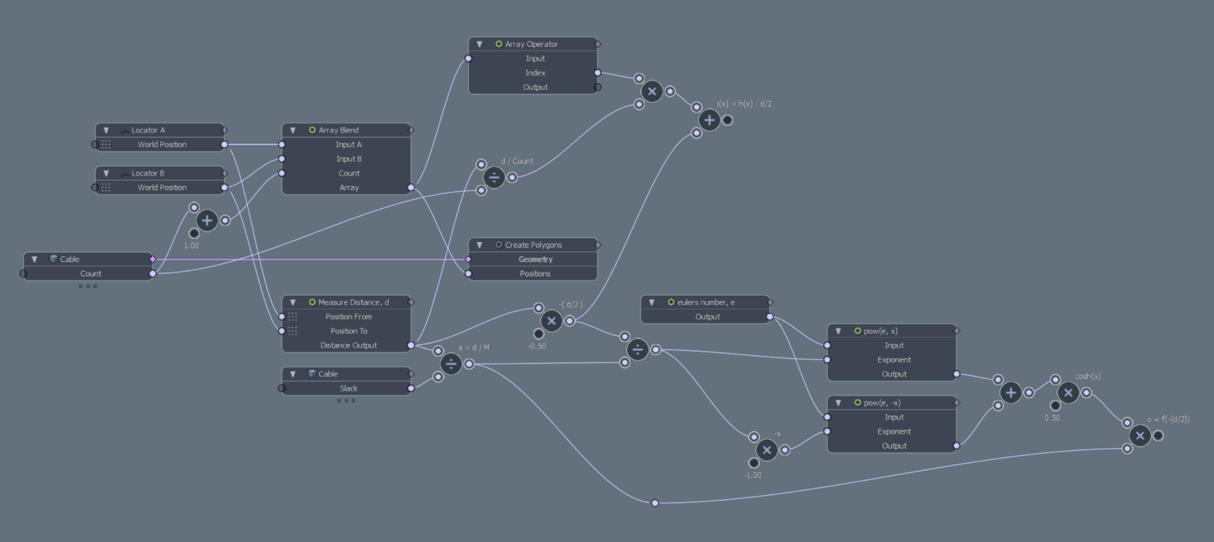
The Schematic View should now look something like this.
Getting into the math
We now have a polygon line between two points that we can control the number of segments for. Time to get into the math of catenary. If you know your math you can maybe make it by just looking at Wikipedia but I am more of a visual learner, so here Desmos really comes in handy. I don't know who to credit this graph to but it really helped me in understanding this.
We will need to know the Distance between our start and end point. To get this we add a Measure Distance node. Connecting our two locator's World Position into Position From and Position To channels. In the Desmos graph this is the variable d. This is needed to solve the variable a. Which in Desmos is defined as a = d / M. M variable has a input slider to adjust the slack of the line. M we will make a user channel for called Slack. To control how taut or slacked the line should be, close to zero is taut while higher numbers will make the line more slacked.
Add the user channel Slack to the mesh item, and add Basic Math:Divide to the Schematic View. Connect the Measure Distance output to the first input of the divide node and our new user channel to the second one. To make things more clear in our Schematic view we can Separate Channel to get two nodes for our mesh, one with the Count, and the other with Slack.
We can now solve the variable o from the Desmos graph, o = f(-d*0.5). Where f is a function f(x) = a * cosh(x/a). Modo does not have the hyperbolic functions like cosh that we will need, so we will have to implement it. This one I can understand well enough from Wikipedia, cosh(x) = (pow(e, x) + pow(e, -x)) * 0.5
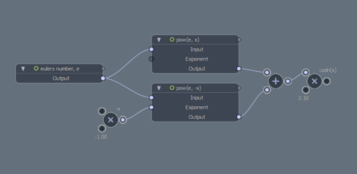
Add a Math:Constant node, and in it's properties change the Constant to Eulers Number. Then we add two Math:Power nodes - exposing the Exponent channel for both. Add a two multiply nodes and one add. For one of the multiply, set the second value to negative one and connect it to one of the power node Exponent. Set the second multiply node to 0.5 to divide by half. Connect the output from the power nodes to the add node, to sum their values. And the output from the add to the multiply by half.
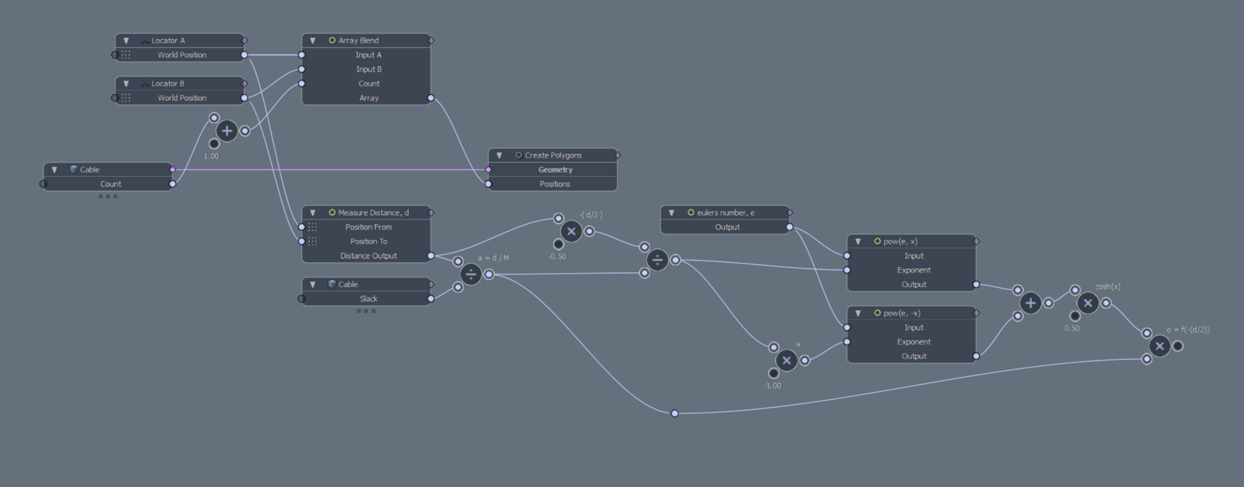
Now with cosh available, create a node to multiply distance d by negative 0.5 to be the input for the function f. The function takes our input. Divides it by a, which we solved earlier. This is used for the cosh and finally multiplied with our a variable.
We will now tackle the function h(x) which I understood to be - how far along the straight curve we are. Connect the distance d to a Basic Math:Divide and in the second input for the divide, plug in our user channel Count. Then add an Array Operator node, and expose the channel Index. Multiply the Index with d / Count and we should have h(x) solved.
Solve the function j(x) = x - d/2. As we already have -d/2 from before, d * 0.5. The input x for j(x) is the result from the function h(x) that we solved in the previous paragraph.
Copy the nodes that we made earlier to solve cosh. Plug the result from our previous step j(x) into a divide with a. Connect the result from the divide to the exponent of one of the power nodes, and the multiply by negative one that goes into the second exponent. Multiply the result from cosh with a, we will call this node j. Then finally subtract o - j.
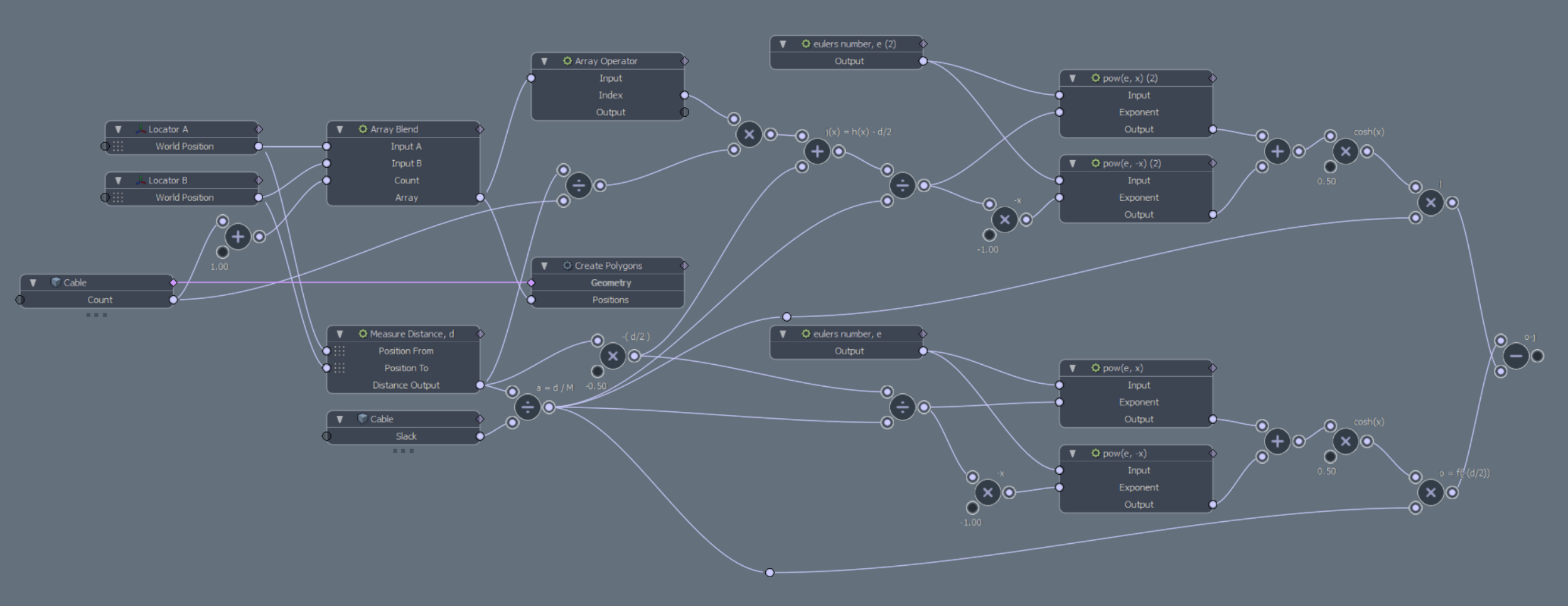
Applying the offset
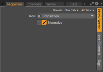
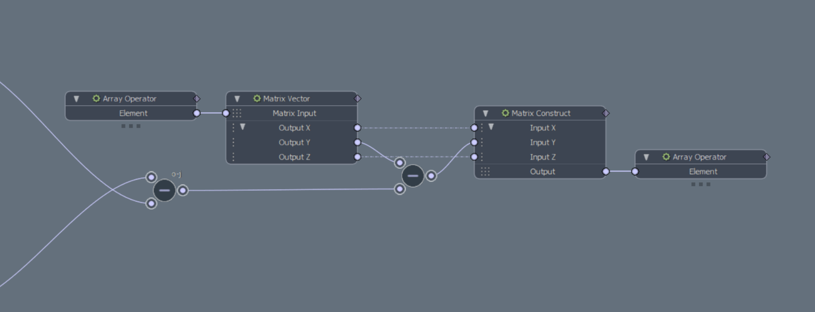
With the math out of the way we can now start applying the offsets to our array of positions. Add both Element channels to the Array Operator node. Right click the Element output channel and Separate Channel. Add a Matrix Vector node and change it's Matrix Row to Translation. Connect the separated Element output to the Matrix Input. Now depending on your world up - Y in my case. Expand the outputs and subtract Y with o-j node from previous.
Add a Matrix Construct and set the Matrix Type to Position. Connect the X & Z from the Matrix Vector to the X & Z for this Matrix Construct, and connect the Y - (o-j) to the Y. Right click the Element input from the Array Operator and again Separate Channel. Then connect the Output from the Matrix Construct to the Array Operator Element input.
Separate the Array Operator's Output and connect to the Positions of Create Polygon, replacing the previous connection. You should now be left with catenary polyline with controlls for slack and number of segments.
Notes
Saw that in a recent video from Modo Geeks TV that Steve Hill have this implemented in his kit Harry, available at Gumroad. But with better controlls, with fixed length and more.